Troubleshooting Tips for Stand-Alone PV Systems
Diagnosing a solar system that is experiencing issues can be challenging if you’re not familiar with the appropriate methodology and tools. This page is meant to help guide technicians and users in quickly identifying the issues & implementing the appropriate solution.
Introduction
Well-designed off-grid solar systems should be able to operate reliably in all but the most extraordinary weather events.
Well maintained & high quality VRLA solar batteries should last approximately 5-7 years before needing replacement. Non-battery components in a well-designed system should last 20 years or more.
Despite this, components do fail, technicians occasionally accidentally leave breakers in the off position, and there are many other issues that can require system diagnosis.
This page is meant to help users quickly identify the source of problems in an off-grid system design using thorough guidelines.

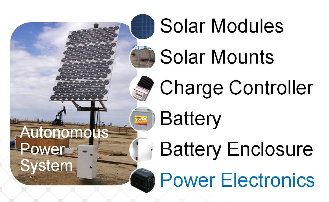
Major System Components
Major Off-Grid System Components Include:
*To protect batteries from becoming permanently damaged, system’s will disconnect the load using a Low Voltage Disconnect “LVD” if battery energy (“State of Charge” or “SOC”) drops below 20%!
Minimum Suggested Equipment
Required for any field troubleshooting:
1. Multi-meter for measuring DC voltage, current, and AC voltage (if necessary)
2. Insulated screw drivers
3. Wrenches for battery terminals
Additional Helpful Equipment
Recommended for any field troubleshooting:
1. Wire stripper/crimper
2. Extra wire for replacements
3. Electrical tape
4. Fresh batteries for measurement / replacement
5. Spare 150VDC breakers
6. Field capable battery charging device
Preliminary Considerations
Before beginning actual technical troubleshooting, take notes on several pieces of important information that may help you resolve system performance issues without needing to take electrical measurements!
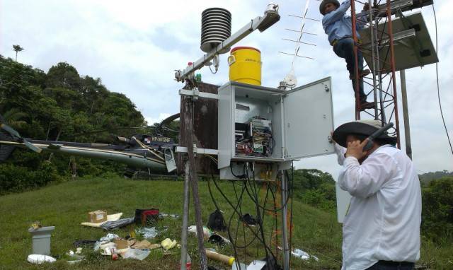
- Visual Inspection – Before opening the control and battery enclosures walk around the system and look at the array, the wiring from the array to the combiner, the control enclosure and the battery enclosure. Note any damage or changes to the systems appearance.
- Verify Installation – Compare the installation to the factory requirements, has the system been installed correctly, mechanically as well as in relation to the sun.
- Load Verification – Verify that the load being consumed by the system is consistent with the original design expectations. If the current load is larger than what was designed for, re-evaluate your design. Visit our IEEE 1562 Sizing tech-note page for details on appropriate design considerations.
- Shading Considerations – Make sure the solar array is in full sun exposure throughout day and is not shaded at all. If unfamiliar with shading effects for solar arrays, please read our tech notes page.
- Breaker Settings – Make sure that all appropriate circuit breakers are in the “on” position.
- Weather – Has there been an abnormally long period of cloud cover at the site? Recent weather history may give clues to system performance or failures.
- Temperature Compensation – For best system performance, we strongly recommend all charge controllers should have temperature compensation included.
- Battery Quality – Solar batteries are primarily measured in cycles, between 500-1000 cycles at 50% Depth of Discharge (DoD) is the typical range for VRLA batteries. If your batteries are failing prematurely, make sure you’re using quality deep cycle batteries and keeping them properly charged.
- Array Positioning – For systems in North America, solar arrays should always be pointed due south. Solar arrays should be tilted at between approximate 45° and 65° depending on your exact latitude.
Troubleshooting
Once you have addressed the above considerations and feel confident that the system is designed well, installed correctly, and positioned properly, but still failing, follow these steps:
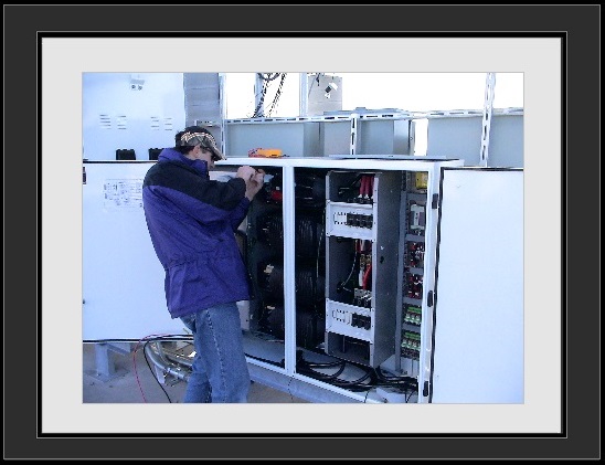
- Open the control, combiner and battery enclosures –
- Inspect the interior of these enclosures for any damage or potential issues.
- Check the circuit breakers are not tripped.
- Locate the Charge and Load controllers and confirm their operational status via the meter or the LED displays on the front of each unit.
- Check Wiring Terminations –
- Ensure that all wire terminations are tight.
- Make sure no corrosion is present.
- Make sure wires are not chaffed.
- Load Verification – Is there a voltage at the load? If there is no voltage, measure voltage on each piece of equipment leading back to the solar array until you find where the voltage and/or current drops.
- Batteries – We’ll be releasing a detailed troubleshooting guide specifically for batteries, stay tuned!
- Check and record each individual battery voltage. Large deltas between batteries or cells can indicate a problem. Replace or recharge problem batteries.
- Verify all interconnections between the batteries are tight & corrosion free.
- If the battery voltage is between 11.5V and 12.6V (23.0V and 25.2V for a 24V system), check the LVD controller battery status LEDs. If LED is red, load has been disconnected to protect battery.
- Consult the charge controller manual for other LED colors or flashing sequences.
- Check for any signs of swelling, shrinkage, or case cracks, these may indicate battery damage.
- If the batteries are not damaged, but are at a low state of charge (indicated by a low voltage measurement), then the system may simply need to have the batteries recharged. This can be done by charging batteries in the field using a portable battery charging unit or swapping the batteries out while they’re charged off-site. Batteries can take 24 hours to fully recharge.
- Solar Array – The two most important numbers when troubleshooting the array are the Short Circuit current (Isc) and Open Circuit voltage (Voc). Refer to module data sheet for both values.
- Voc – The Voc should be fairly consistent between each module in your array and should be around 20-22VDC for a 12V nominal array and 40-44DC for a 24V nominal array. The voltage is minimally affected by sunlight conditions.
- Isc – The short circuit current (Isc) should ideally be tested on a sunny day around solar noon. It will be linear with the sunlight conditions. So if only 50% of irradiance is available, then the current will be reduced by 50%. If an irradiance meter is not available, and you have multiple strings, a comparison between the strings can indicate a problem.
- All electrical measurements for the solar array should be taken at both the individual module, as well as, the individual array string level. Discrepancies between module or array measurements may help to indicate problems.
- Using a Multimeter – Once all the above issues and concerns have been addressed, it’s time to begin measuring electrical parameters (voltage and current) on each side of our electrical devices to look for any faulty components. With all components on, we will attempt to trace the voltage from the load to the solar array, through each electrical device.
- Check voltage on load side and battery side of Load Controller
- Check voltage of battery bank
- Check voltage on either side of any load breakers
- Check voltage on either side of any battery breakers
- Check voltage on battery side of charge controller
- Check voltage on either side of any array breakers
- Check voltage on array side of charge controller
- Check voltage at the individual module and array string levels (check combiner box if present).
- Check any other power electronics that may be in circuit, such as DC-DC Converters or AC Inverters.
Summary
After recording voltage and current for each device through the system (refer to wiring diagram if available), it should be apparent if there are any faulty devices. Typically there will be valid input voltage or current into one side of the device (input), but nothing or bad values coming out of the other end of the device (output). Refer to the instruction manuals for appropriate input/output voltage values for each device. An input voltage on one device may exceed the equipment specifications (perhaps due to unexpectedly hot temperatures) and therefore may be failing even though the device is not faulty).
Example – there may be appropriate voltages all the way through the circuit from the solar array to the input side of the battery breaker, but no output voltage at this breaker. This would indicate a faulty or broken breaker, and we would recommend replacing that breaker to see if it resolves the issue.