Introduction to Solar Battery Basics
SunWize has been designing and building reliable solar and battery backup systems for leading governments and industrial customers for over 25 years. Our experience working with demanding mission critical applications and harsh conditions gives us unique insight into what it takes to successfully design, build, and maintain solar and battery backup based systems that will work and last!
Topics Overview:
- Battery Safety
- Terminology
- Series vs Parallel
- VRLA vs Lithium
- Charging Parameters
- Cycle Life
- Temperature Effects
- Logistics
Want Even More In-Depth Information on VRLA Batteries?
SunWize suggests reviewing the below technical manuals from these leading VRLA battery manufacturers!
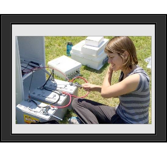
1. Battery Safety
The first and most important consideration when working with batteries is always safety, as even sealed batteries can have the potential to be harmful, or even deadly, if not treated with proper care.
For a more comprehensive overview of battery safety we suggest reviewing both of the below:
- IEEE 937-2007 Recommended Practice for Installation and Maintenance of Lead-Acid Batteries for Photovoltaic (PV) Systems – Available for Purchase Here
- MK Deka – Safety Precautions Section of the Guide to VRLA Batteries
Below Per Excerpts From IEEE 937
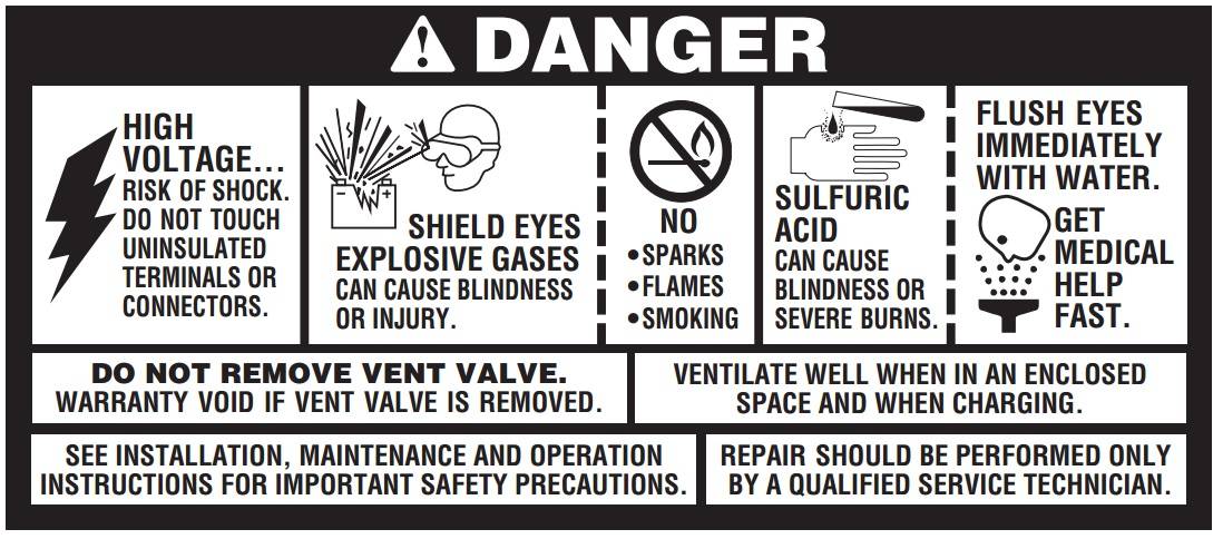
Battery Safety Overview
The guidelines discussed below should be followed anytime you’re working on or around batteries. Work performed on batteries should be performed with proper protective equipment and tools. Battery installation should only be performed by personnel knowledgeable on required safety precautions.
Safety Gear
The following equipment is recommended for safer handling of lead-acid batteries and protection of personnel:
- Goggles, safety glasses, or other suitable eye protection
- Insulated Grip Tools
- Protective clothing and overshoes, preferably with gloves, that leaves no exposed skin
- Eye-wash stations
- Baking Soda or other acid neutralizer
- Forklift or other lifting device if batteries are very heavy
- Fire extinguisher
Safety procedures
The below are all risks associated with handling batteries. Follow the guidelines below to minimize safety hazards.
Electrical Safety Tips
Electrical shock can occur from batteries if they are short circuited. Use care when handling or in potential contact with battery terminals. Always follow these procedures:
- Do not wear any metallic objects while working with batteries, as these may cause unintended short circuits
- Don’t use any metal tools without insulated handles
- Rubber or plastic protective gear can help minimize risk to electrical shock
- Check if battery is unintentionally grounded
- Make sure all loads and charging sources are de-energized before working on batteries
Electrolyte Safety Tips
The electrolyte used in batteries is made of sulfuric-acid liquid. The electrolyte can not only conduct electricity but is extremely toxic. Always follow these procedures:
- Use proper protection for clothing and eye wear
- If electrolyte solutions is exposed to skin, immediately wash it off
- If electrolyte solution is exposed to the eyes, use eye wash station to thoroughly rinse eyes, then reach out for professional medical help
- Always neutralize any spilled electrolyte, using Baking Soda or similar
- Spilled battery acid is a hazardous waste if not properly disposed of
- Any containers that have been in contact with battery electrolyte also need to be properly disposed
Fire Safety Tips
VRLA batteries produce hydrogen gas through a process known as off gassing. Because of this, there is a fire present danger from igniting the hydrogen gas. Always follow these procedures:
- Never put a battery in a completely sealed environment
- Do not smoke near batteries
- Do not have any open flames near batteries
- Touch a grounded metal surface before working with batteries to discharge any static electricity
Handling Safety Tips
Batteries can be extremely heavy. Use appropriate care when lifting and moving batteries by following these steps:
- Verify any lifting devices are adequately rated and functioning properly
- If storing on shelves or racks, make sure they are secure
- Do not drop batteries or allow any significant impacts to battery
- Keep batteries upright
General
Always follow these general tips as well:
- Verify there is clear exit path from battery area
- Keep unauthorized people out of the battery area
- Do not ever place any objects on the top of the batteries (near terminals)
2. Terminology
- Ah Charge Efficiency: Ah charge efficiency is calculated by dividing the Ah discharged by the required Ah charged to maintain battery capacity under specific cycle and charging conditions.
- Autonomy: The amount of time a fully charged battery can satisfy the load with no contribution from the photovoltaic array or auxiliary power source. See also: Days of Battery Reserve.
- Battery Conditioning: Battery conditioning charges a battery to its full capacity after performing multiple cycles. Battery conditioning is designed specifically for obtaining maximum new battery capacity.
- Battery Group Size: Most VRLA batteries fall into the internationally adopted Battery Council International (BCI) group’s size definitions, such as group numbers 24, 27, 31, 4D, 8D, L16, etc.
- Capacity (C): Generally, the total number of ampere-hours that can be withdrawn from a fully charged battery at a specific discharge rate and electrolyte temperature, and to a specific cutoff voltage.
- Charge Controller: An electrical control device that regulates battery charging by voltage control and/or other means. The charge controller may also incorporate one or more of the following functions: discharge termination, regulation voltage temperature compensation, load control, and status indication.
- Cycle Life: The number of cycles (discharges and recharges), under specified conditions, that a battery can undergo before failing to meet its specified end of life capacity.
- Days of Battery Reserve: The number of days a fully charged battery can satisfy the load with no contribution from the photovoltaic array or auxiliary power source. See also: Autonomy.
- Depth of Discharge (DOD): The ampere hours removed from a fully charged battery, expressed as a percentage of its rated capacity at the applicable discharge rate.
- Discharge Rate: The rate, in amperes, at which current is delivered by a battery. See also: hour rate.
- Dry-Charged Cell: A cell that does not contain electrolyte for ease in shipping or storage, or both.
- End-of-Discharge Voltage: The battery voltage just prior to load termination. EODV will be the minimum voltage for the given discharge cycle.
- Energy Capacity: The energy, usually expressed in watt hours (Wh), that a fully charged battery can deliver under specified conditions.
- Equalizing Voltage: The voltage, higher than float, applied to a battery to correct inequalities among battery cells (voltage or specific gravity) that may develop in service.
- Freshening Charge: The charging of batteries to assure that they are maintained “fresh” in a near-maximum state of charge, and to assure that there is no deterioration of the battery plates due to self-discharge and resulting sulfation. Freshening charges are usually performed using the manufacturer’s recommended equalization or cycle-service charging voltage.
- Hour Rate: The discharge rate of a battery expressed in terms of the length of time a fully charged battery can be discharged at a specific current before reaching a specified end-of discharge voltage.
- Low Voltage Disconnect (LVD): The battery voltage at which the load is disconnected to prevent over discharge. The LVD is the determining factor for the actual maximum allowable depth of discharge and available battery capacity in a PV system.
- Life: The period during which a fully charged battery is capable of delivering at least a specified percentage of its capacity, generally 80%.
- Overcharge: The number of ampere-hours charged divided by the number of ampere-hours discharged times 100. Typical overcharge values are between 105 and 130%.
- Pilot Cell(s): One or more cells chosen for monitoring the operating parameters, e.g., cell voltage, specific gravity and temperature, of the entire battery.
- PV Array to Load Ratio (ALR or A:L): The photovoltaic (PV) array Ah to load Ah ratio is the monthly daily average PV ampere-hours available divided by the monthly daily average load ampere-hours. Average daily PV ampere-hours are calculated by taking the daily average solar resource for each month in kWh/m2 times the PV array current at its maximum power point (Imp) at standard test conditions (STC). Array to load ratios can also be calculated in terms of their respective Watt-hour parameters.
- Rated Capacity (C): The capacity, in ampere hours (Ah), assigned to a cell by its manufacturer for a given constant-current discharge rate, with a given discharge time, at a specified electrolyte temperature and specific gravity, to a specific endof-discharge voltage.
- Regulation Voltage: The maximum voltage that a charge controller will allow the battery to reach under charging conditions. At this point the charge controller will either discontinue charging or begin to taper the charging current to the battery.
- Self Discharge: The process by which the available capacity of a battery is reduced by internal chemical reactions (local action).
- Self Discharge Rate: The amount of capacity reduction in a battery occurring per unit of time as the result of self discharge.
- Standard Test Conditions (STC): The accepted conditions under which PV devices are commonly rated: 1000 W/m2 irradiance at a spectral distribution of airmass (AM) 1.5 and a 25C PV cell temperature.
- String: Refers to a group of batteries wired together in series to some nominal voltage (usually 12, 24, or 48V). Can also be referred to as a group of solar modules wired in series.
- Vented Battery: A battery in which the products of electrolysis and evaporation are allowed to escape freely to the atmosphere. These batteries are commonly referred to as “flooded.”
- Valve-Regulated Lead-Acid cell (VRLA): A lead-acid cell that is sealed, with the exception of a valve that opens to the atmosphere when the internal gas pressure in the cell exceeds the atmospheric pressure by a preselected amount. Valve-regulated cells provide a means for recombination of internally generated oxygen and the suppression of hydrogen gas evolution to limit water consumption.
3. Series VS Parallel
Wiring solar batteries into the proper configuration is relatively straightforward if you know the rules! When batteries are wired together in Series their voltage is increased but their capacity (Ah) remains the same. When batteries are wired in parallel their voltages remain the same but their capacity (Ah) is increased.
By wiring batteries together in different Series and Parallel combinations, you can achieve a battery bank that gives the appropriate rating (accomplished through wiring strings of batteries together in parallel) at the appropriate voltage (accomplished through wiring your batteries together in strings to the desired design voltage).
Generally, battery banks are wired in nominal 12V, 24V, or 48VDC configurations. In addition, batteries are usually limited to (4) or less strings in parallel (for battery performance and reliability).
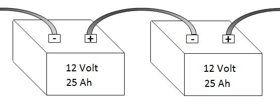
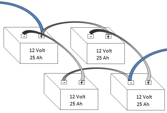
Batteries Joined in Series
Connecting batteries in Series will increase the voltage of the battery “string”, but will not increase its capacity. For example, two 12V batteries rated for 25 Ah wired together in series will produce a battery string rated for 25 Ah at 24V.
(x2) 12V batteries rated at 25Ah wired in series = 25Ah at 24V
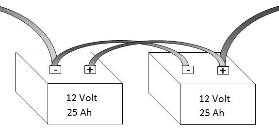
Batteries Joined in Parallel
Connecting batteries in Parallel will increase the capacity of the battery bank, but will not increase its voltage. For example, two 12V batteries rated for 25 Ah wired together in parallel will produce a battery string rated for 50 Ah at 12V.
(x2) 12V batteries rated at 25Ah wired in parallel = 50Ah at 12V
Batteries Joined in Series & Parallel Together
Using the above rules for connecting batteries in series and parallel, batteries can be wired together to form whatever rated capacity the system design dictates. For example, if your design required 50Ah of energy storage at 24VDC, then one possible solution would be (x2) strings of batteries rated at 25Ah each.
(x4) 12V batteries rated at 25Ah wired series (24V) and in parallel (50Ah) = 50Ah at 24V
Other Wiring Considerations
In general, it’s not recommended to have more than 4 strings of batteries in parallel together. The reason is that internal resistance from wire, connections, etc. can create imbalances in the way currents are shared between batteries. Over time, this causes some batteries or strings to get used more than others and causes them to fail prematurely.
As more batteries are wired in parallel the risk increases for failed connections or batteries. Always remember to use the same wire size and length between batteries, even if it’s possible to use shorter lengths. Keeping the lengths consistent will keep your battery bank charges evenly distributed among strings and batteries! Always make sure your battery connections are clean of debris and corrosion!
When using multiple batteries, it’s important to not mix and match different batteries, even if they appear similar! If possible, do not mix new and used batteries either. Any small differences in battery health, chemistry, or target voltages can result in poor performance, failure, or become a safety concern.
4. VRLA vs Lithium
By now nearly everyone is familiar with Lithium Ion Battery Technology and its different variants for consumer technologies. What people are less familiar with are lithium batteries for industrial energy storage applications. Specifically, SunWize receives many questions on the differences between “lead-acid” or “VRLA” batteries and Lithium based batteries, including Lithium Ion (Li) and Lithium Iron Phosphate (LFP). Customers that are exploring these new technologies often want to know if their applications are a good fit for some of these advanced batteries and what the hurdles are.
Morningstar recently released a white paper detailing functionality and settings for using their charge controllers with NEC Energy ALM series advanced Lithium Batteries! We suggest reading this white paper if you’re interested in using Lithium batteries in solar applications!
Preliminary Considerations
Whether a traditional VRLA battery or an advanced chemistry battery is right for your application depends on a host of factors. While the below are not exhaustive by any means, we suggest starting here.
Length of Project
Projects that have intended lives well in excess of typical VRLA battery lifespans are good candidates for advanced battery technology. When factoring in the total lifetime cost of replacing batteries (labor, travel expenses, future batteries), investing in the extra longevity of some advanced chemistry batteries may result in overall cost savings during the life of the project.
Cost of Battery Replacements
When factoring in the total life cost of a system, remember that there may be unforeseen failures and/or battery replacements beyond just the scheduled replacement interval. If the project is in a particularly hard to reach location, the travel expenditures of replacing a set of batteries may be thousands of dollars for the batteries alone. For projects that involve high cost of travel to the system, spending additional money up-front on longer lasting batteries may save money in the long run!
Extreme Environments
Many VRLA batteries are built to withstand extremely harsh conditions. However, the limitations of the battery chemistry mean that in extremely cold and warm environments VRLA batteries have major drawbacks. At extremely cold temperatures (in excess of -15°C) VRLA batteries can and will freeze if experiencing particularly cold temperatures at low state’s of charge (SoC). At sustained high temperatures, the life span of VRLA batteries can be significantly reduced. In these extreme temperature conditions, there are some advanced batteries with design temperature ratings well outside of VRLA battery capabilities!
Space Limitations
Sometimes projects or applications are overly constrained with regards to space requirements. In cases where there simply is not room to scale or add additional batteries, going with high power density batteries may be the only way to achieve the required design.
Power Requirements
In certain specialty applications there may be exceptional power input or output requirements for the batteries. For instance, if an exceptionally fast recharge time is required there are many advanced batteries capable of receiving many times the amount of energy as VRLA batteries during charging. Similar, if very fast power discharge is required, while AGM batteries can perform very well at this task, they still will not compare to the power density output capabilities of some advanced batteries.
5. Charging Parameters
Most solar charge controllers and battery chargers operate in 3-stages. These are known as the Bulk, Absorb, and Float stages. Sometimes it’s important to understand what the various specific charging characteristics are for individual batteries, how to find that in the manufacturer’s literature, and then how to apply that to your system design!
3 Stages of Battery Charging
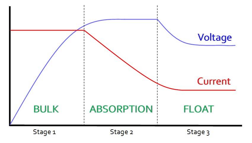
Stage 1 – Bulk Charging
Bulk charging is the first stage of battery charging and occurs when a mostly or completely drained battery begins to get charged. The charging source could be a solar charge controller, a dedicated battery charger, or an inverter-charger in charge mode. In this bulk charging phase the charger is giving the batteries a constant amount of current (shown as the red line on the above chart). As current (amps) flows into the battery over time (horizontal axis), the voltage on the battery begins to rise (blue line).
In Bulk charging the current to the batteries is constant, while the voltage of the batteries Increases. The majority of energy delivered to the battery occurs during bulk charging stage, as the battery is able to receive energy easily when fully discharged. When the battery voltage reaches a sufficient value, the charger moves from Stage 1 Bulk charging into stage 2 Absorption charging.
Stage 2 – Absorption Charging
The second stage of battery charging is Absorption charging. In this stage, the battery voltage essentially stays constant (blue line) while the amount of current (red line) feeding into the battery decreases. At the end of the absorption stage a battery will be fully charged.
While bulk charging is responsible for bringing the battery to 80%-90% of its energy capacity, the remaining 10%-20% is extremely important for the long-term health of the battery in order to prevent sulfur build-up on the battery plates, which significantly affects battery performance and life.
Stage 3 – Float Charging
The third stage of battery charging is float charging. In this stage, the battery has reached a state of full charge and begins to maintain a constant voltage and current in order to keep the battery at the optimized voltage and current for maximum battery longevity.
Charging Times
Many people incorrectly assume that because a battery shows a certain voltage during charging that it must be full! This is incorrect as the voltage on the battery will be affected by the charging source! Only batteries that have been at “rest”, no charging or discharging, for quite some time (several hours to a full day) display a correct voltage.
Typical battery recharge times from an empty state of charge to a full state of charge, when the charging source has unlimited power, are roughly at least 5-7 hours or longer. During this time period the battery frequently reaches 90% state of charge after roughly half the recharge time, and takes the entire other half to gain the remaining 10%. However, as we mention above, this last 10% is extremely important so do not remove the charging source prematurely!
Voltage Setpoints
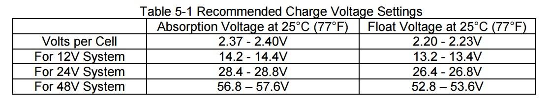
While most solar and battery charging products will have a default setting for VRLA batteries that should work with your batteries out of the box, sometimes it’s important to understand what the voltage set points are and how they’re used. In cases of custom programming, or unusual temperature environments, it is necessary to understand what the optimal charging set points are for your specific battery. This can be found on either the battery data sheet, or the technical manual for the battery manufacturer. If you’re unsure, we recommend using the set points provide by one of the manufacturer technical manuals at the top of the page. These Gel and AGM settings will work with most Gel and AGM products.
Table 5-1 below from the Concorde Technical Manual lists typical Absorption and Float voltage setpoints for the Sun Xtender line of AGM batteries.
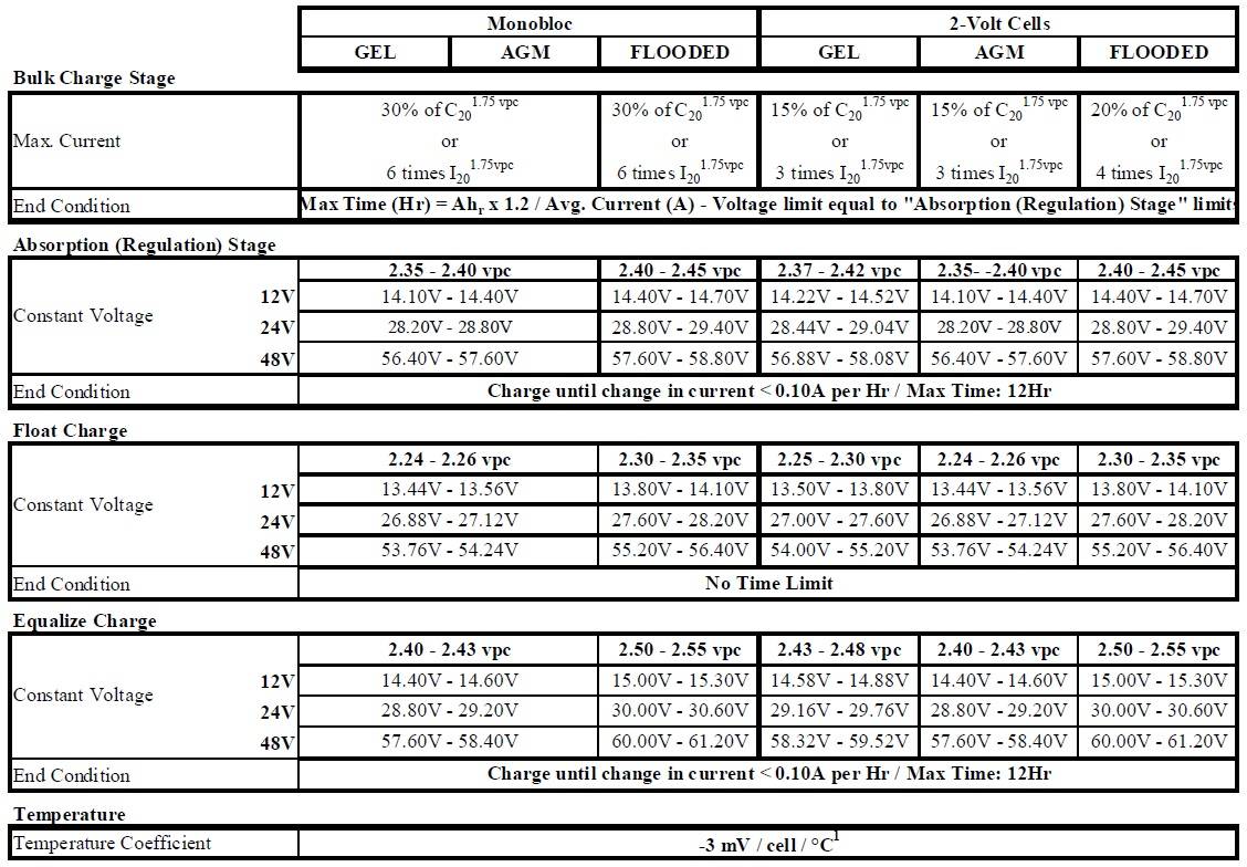
The below table from the official MK Deka Charging Parameters document illustrates detailed set point information for Gel batteries.
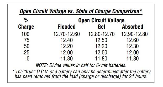
Are My Batteries Charged?
The below table from the MK Deka Technical Manual helps to easily illustrate corresponding State of Charge (SOC) values, or how much energy is in the battery, with the battery voltage. In summary, battery voltages that are between 12.6V to 12.8V are at or near full state of charge. Batteries that are between 11.8V to 12.0V are at or near an empty state of charge.
Note the manufacturer recommends leaving the batteries “at rest”, no charging or discharging, for a full 24-hours before testing the battery voltage!
6. Cycle Life
The most defining characteristic of a solar battery is its cycle life. The “Cycle Life” of a battery refers to the number of times a battery can go through a full charge discharge cycle, to a specific discharge level. The last part is particularly important as batteries have different cycle life’s depending on how deeply they’re discharged! A battery that is always discharged to 80% Depth of Discharge (DOD) during each cycle will last much less time than a battery that is only discharged to 20% Depth of Discharge (DOD) each cycle. Of course, the battery that’s discharged to 80% will give you significantly more energy per cycle than the battery discharged to 20%!
The reason Cycle Life is so important to solar battery systems is that solar battery systems cycle daily (during night when the sun goes down and during extended periods of cloud cover). In contrast, batteries in many other applications, such as those attached to the grid, may only cycle very infrequently, such as when there’s a power outage.
Therefore, if using batteries in a solar powered application, make sure they’re designed specifically for solar applications and list a Cycle Life rating. If the battery does not have a Cycle Life rating, it is likely not designed for solar applications and will fail prematurely compared to a battery that is designed for cycling applications.
High quality solar batteries that are designed and operated properly should expect lifespans between 5-8 years. If your batteries are lasting significantly less than this it’s usually because of some combination of:
- Lower quality battery or not designed for solar applications
- System not properly designed resulting in over discharged battery
- Not properly maintaining battery health, such as quickly recharging to full health after a low voltage disconnect (LVD) event.
Premium VRLA batteries often are rated for 1,000 Cycles or more at a 50% Depth of Discharge rating. Some advanced VRLA batteries are higher than this, but it’s generally not by a tremendous amount, Other advanced chemistry batteries, such as Lithium Ion or LFP, on the other hand, may have Cycle Life ratings as high as 10,000 cycles or more.
7. Temperature Effects
Temperature has a major effect on battery performance. Both low temperatures and high temperatures can significantly impact battery performance, both in the short term, as well as, the long term. Extreme temperature’s, if not properly designed for, will almost certainly result in battery failures.
In addition to the general effects of extreme cold and warm weather on batteries, charging devices may have additional temperature compensation features that should be set. To see detailed information on this, review our Battery Temperature Compensation Tech Note.
Cold Weather
Cold temperatures primarily affect batteries by limiting the amount of energy that is able to be released. While a typical battery may have 50 Ah of usable energy at room temperature, that same battery may only have 25 Ah of usable energy at -15°C. Therefore, if installing batteries in climates where extended temperatures are significantly below ambient, it’s important to apply a proper temperature de-rate to the battery so that, even in the coldest weather, you have the appropriately designed amount of energy storage available. If the system requires 200 Ah of usable energy storage to operate properly, but you install it in an environment that de-rates that battery energy in winter from 200 Ah to 100 Ah, then you only have half the required energy in your system design!
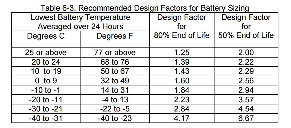
The below Table 6-3 from the Concorde Technical Manual illustrates temperature de-rates for AGM batteries. Note that in addition to cold temperature de-rate affects, batteries can also “freeze” if discharged too far in cold weather. Therefore, when designing batteries in extremely cold weather, take into account both the freezing point and the appropriate de-rate values!
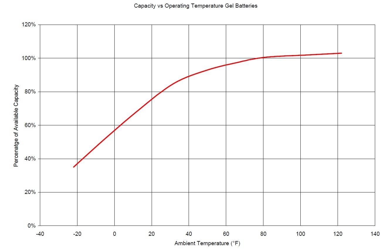
The below chart from MK Deka illustrates the same information as Table 6-3, but gives the de-rate values rather than the design factor values (simply the inverse of eachother). Table 6-3 is an excellent reference point for AGM batteries while the below chart from MK Deka is a great reference point for Gel batteries.
Example: at -15°C the de rate value according to MK Deka is ~50%, therefore you would need 2x the rated battery capacity at these temperatures (rated capacity divided by 50% = 2). According to Table 6-5, between -11°C and -20°C (roughly the same temperature), the design factor is 2.23x, or very close to the 2x value for the Gel battery.
Hot Weather
Hot temperatures primarily affect batteries by decreasing the overall lifespan of the battery. In general, for every 13°F above ambient, a battery will experience a 50% total loss of lifespan. Therefore, at sustained temperatures of 107°F (30°F above ambient of 77°F) a battery will last only 25% of its rated life!
In addition, off gassing, thermal runaway, and other issues related to extreme warm climates also exist. In these cases, the batteries are generally actively cooled or buried underground for passive cooling.
8. Logistics
For information related to packaging and shipping VRLA batteries, see our Solar Battery Recycling & Storage page for more info!
More Battery Info!
Still looking for more information related to batteries?
Click Here to shop batteries on our online store, SunWize Connect!
Click Here for our Tech Note on Battery Temperature Compensation.
Click Here for our Tech Note on Gel vs AGM Batteries.
Click Here to contact us if you still can’t find what you’re looking for!