Introduction

Solar charge controllers are essential in off-grid solar systems. This page will provide an overview of different charge controller types and their uses. Knowing what type of charge controller you have and how it operates can help you to troubleshoot and understand if your controller is functioning correctly. To learn more about general information on Solar Charge Controllers themselves, visit our page, Solar Charge Controllers – General Overview.
Primary Function
The primary function of a solar charge controller is to prevent the battery from being over/under charged by the solar array. Most charge controllers have various setpoint points for regulation based on battery voltages; these setpoints can be fixed or variable. Variable setpoints can be adjusted by potentiometers, dipswitches, jumpers, displays, computers, and other means. The charge setpoints should be adjusted for temperature with either a local or remote temperature probe.
Most charge controllers are a variation of one these four basic types:
- Shunt Regulator
- Series Regulator
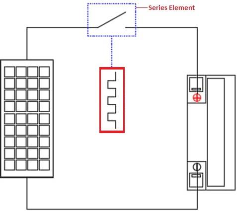
- PWM Regulator
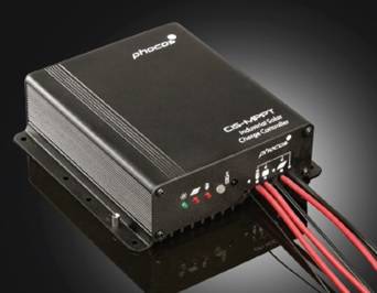
- MPPT Charge Controller
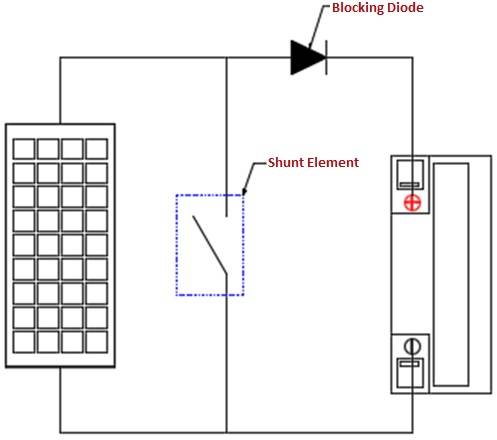
 When the shunt regulator shorts the array during regulation, measuring the array voltage during this time will yield an array voltage that should be less than 1V. During normal charging, the array voltage should be slightly higher than the battery voltage (battery voltage + the voltage drop from diodes or transistors). If array open circuit voltage was ever measured during normal operation, this would indicate a problem.
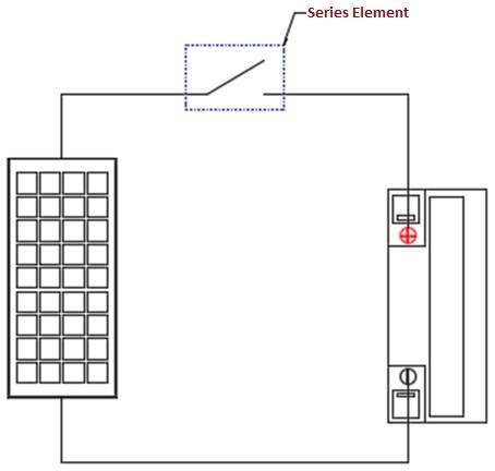
 Like the series regulator, the transistor can be placed in either the positive or negative line, allowing the regulator to be used in positive and negative ground systems.The difference between the series regulator and the PWM regulator is the PWM of the transistor. When the modulation width is at 100% or 0%, the regulator is essentially a series regulator, it is that modulation width variation that allows the PWM regulator to create a constant voltage to the battery as opposed to the on/off of the series regulator. The below figure shows an example of a PWM regulator regulating with a 70% on 30% off duty cycle.
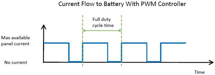
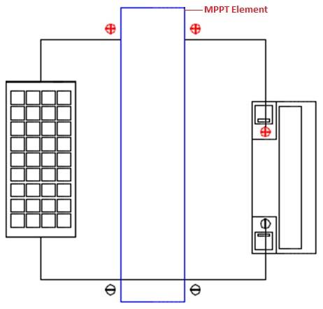 The Maximum Power Point Tracking (MPPT) charge controller takes the PWM to the next level, by allowing the array voltage to vary from the battery voltage. By varying the array input, the charge controller can find the point at which the solar array produces the maximum power. The MPPT process works like this. Imagine having a battery that is low, at 12 V. A MPPT takes a voltage of 17.6 volts at 7.4 amps and converts it down, so that what the battery gets is now 10.8 amps at 12 volts. MPPT controllers takes the DC input from the solar panels, convert it to high frequency AC, and then change it once again to a different DC voltage and current. The point is the voltage will exactly adhere to the requirements of the battery. As the MPPT charge controller uses the negative line as a reference and then switches the positive line, they can be used in negative ground systems only. It is crucial to understand that voltage is a potential difference; the ‘difference’ refers to the difference between ground potential and some potential. This means that the starting point is below zero, but this is only used as a reference point.
 Since MPPT charge controllers can vary the charge current to the battery, the regulator can be a multi-stage charger with bulk, absorption, and float settings. They are always solid state; this means heat dissipation can become a problem, especially in larger solar arrays. MPPT controllers are typically step-down converters, so the array voltage always needs to be higher than the battery voltage. Therefore, an array voltage value less than the battery voltage during normal operation would indicate a problem.
Charge controllers are arguably the most important components of off-grid solar systems. Without them, batteries would be overwhelmed and unable to keep up with the dynamic changes in energy that come from solar panels. When choosing the correct charge controller, it is important to keep in mind the specifics of the project at hand; each controller is applicable for various scenarios and like most things in life require trade-offs. Buy a Solar Charge Controller Here