Introduction to Grounding Basics
 There are three main reasons for grounding in an off-grid power system: safety, voltage transients, and the sheer fact that they are required for some loads. But before we address each of these, it’s important to understand the actual definition of ‘ground’.
There are two types of ground: chassis (or mechanical) and electrical. Both are completely different grounds and must be understood correctly. ‘Ground’ is just a reference point; it does not always mean neutral.
The Definitions
Chassis Ground
– the bonding of all exposed non-current carrying metallic objects (solar module frame, battery enclosure, backplate, array mounting structure, etc) together and eventually to the actual earth.
*Chassis grounds are done primarily for safety reasons. This prevents any possible potential buildup on the metal object that could cause a shock when there is contact with the metal. Remember! Voltage is just the potential difference between ground potential and some potential. Having your system mechanically ground would get rid of the difference. *
Electrical Ground
– the connection of one of the current-carrying conductors to the equipment grounding system and to the actual earth. In a battery based system, it is recommended to connect one of the current-carrying conductors as close to the battery as possible, as the battery is typically the greatest DC source of power.
*As with chassis grounds, one reason to ground the electrical system is for safety; however, electrical transients are another major reason.*
Now with the definition nailed down, we will continue on with a deeper emphasis on electrical grounds!
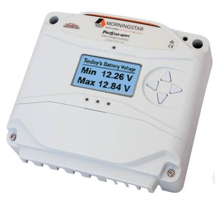 Many charge controllers and other electrical devices in off-grid systems have transient protection that require a grounded conductor for them to function correctly. What that means is both lines must be connected properly in order for the system to work correctly. Surge arrestors are devices that protect the system from over-voltage transients caused by external events, such as lightning. Many of these devices use a grounded conductor to function; without the grounded conductor, there is nowhere to shunt, or divert, the transient. This greatly limits the effectiveness of the surge protector.Additionally, the grounded conductor causes most controllers to be labeled as either negative or positive ground. Switches, fuses, and circuit breakers should not be used in grounded conductors, as this could potentially break the conductors ground. That being said, there is one exception, which leads us on to the next topic.
 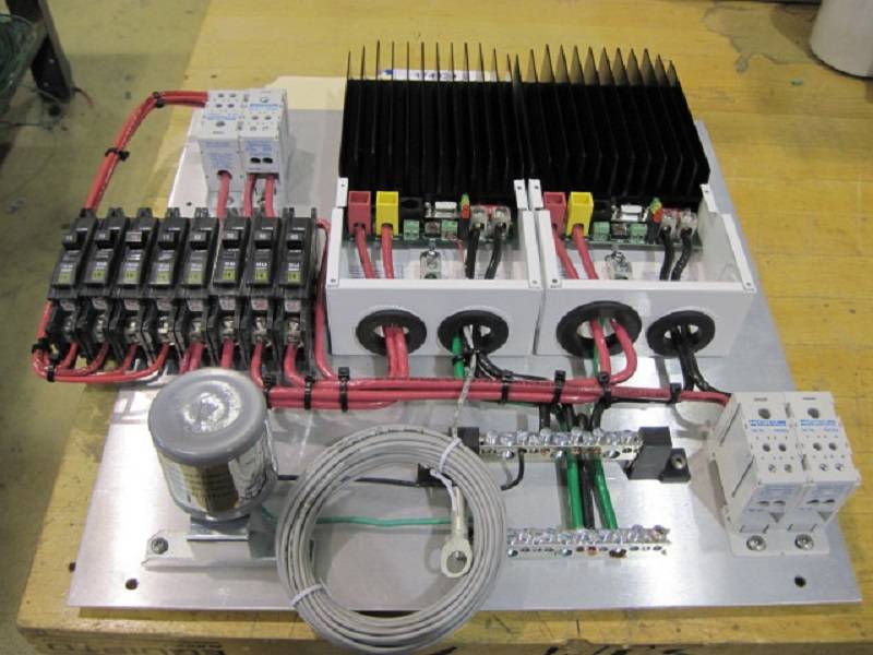 Switches, fuses, and circuit breakers can be used with electrical grounds in the case of mobile systems. Due to the nature of the requirements of the system, a floating ground is used in both off-shore platforms and mobile systems. In mobile applications, it is still advisable to have a common (grounded) conductor that is connected to the actual earth. For this reason, the chassis of the vehicle (car, truck, RV, etc) will typically be used as the electrical ground. Although it is not as ideal as an actual earth ground, it does provide a measure of safety. In off-shore plateforms, it gets a bit trickier, as you can create a galvanized corrosion reaction between the electrical and chassis ground. In order to prevent this from occurring, these systems are typically truly floating and use two-pole breakers to switch both the positive and negative lines at the same time.
  The last reason for electrical grounds are the load requirements. This is obvious in some loads, like cathodic protection systems, where a reverse process is used through impress current to defeat the naturally occurring ground voltage in the area of the pipeline. An electrical ground is required in this reversal process and is absolutely critical to the longevity of a system. If there is too much earth voltage on the pipeline, there will be irreversible damage to the pipe coatings. Understanding what an electrical ground is and how it properly protects vulnerable metal elements like this, helps to cement the difference between an electrical ground and a chassis ground. It should be noted that some loads may connect both the electrical and chassis grounds together within the device-lack of proper care when overseeing these situations can lead to major problems.
 A Few Things to Keep in Mind
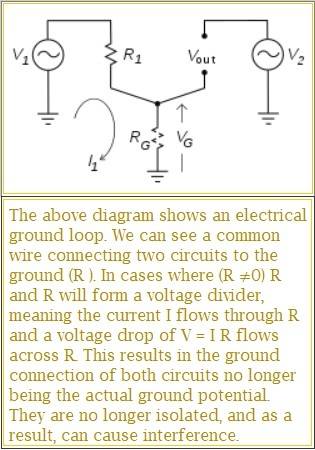
- >> Ground Loops Should Be Avoided: The electrical ground should be connected to the system/earth ground at one point and only one point. Multiple grounds can cause the system and electrical equipment to function incorrectly. This is especially true with charge controllers, as ground loops can create additional paths for current to flow when the controller is trying to regulate.
- >> Connection to both a System Ground and Earth: An earth ground can be created by a ground rod, copper wire in the ground (known as a ground ring), and by other means. A mounting pole can be used as the ground, if installed correctly. However, an earth resistance meter should be used to measure the resistance from the system ground to the actual earth. It is recommended that the ground system have a resistance less than 5Ω to ground.
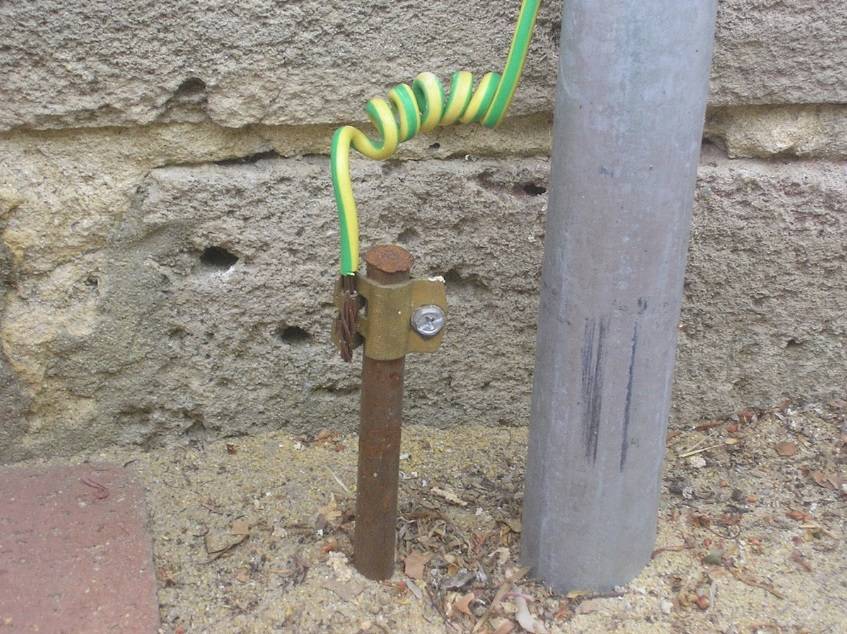
Note: Depending on the soil and site conditions, multiple ground rods may be required to achieve the required resistance.
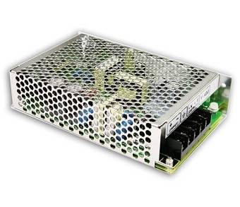
- >> Different Grounds mean using an isolated DC/DC converter: Operating loads with different grounding requirements within the same system can be done using an isolated DC/DC converter. The load can still be grounded; the isolated DC/DC just allows the voltage to be inverted from other loads and systems as well. These types of converters are usually used to improve basic safety, enhance noise immunity, generate dual-polarity rails, and provide galvanic isolation and are used in a broad range of applications.
- >> Connection- Chassis and Electrical:
The connection from chasis grounds to the earth or system ground should be done by copper wire and ground lugs with bonding wires or self-tapping screws, as required. The electrical ground, on the other hand, can simply be made by connecting the grounded conductor to the earth or system ground. Refer to the National Electric Code (NEC) for grounding requirements.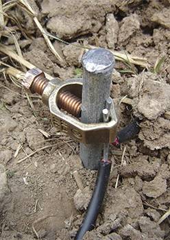
Wrap-up
Understanding the difference between a chassis ground and an electrical ground allows you to maintain an efficient and long-lasting system. While understanding exactly how much current voltage is required in an electrical ground to offset the natural earth voltage is complex, when done correctly, it can prevent corrosion before it becomes visible. Grounding improves the safety in an off-grid system and allows the transient protection to function properly.