solar water pumping basics
Fundamentals of Solar Water Pumping Systems
 Designing and building water collection systems for use in agriculture and for consumption is a practice as old as civilization. One of the fundamental questions for operating off-grid water pumping systems is where the power will come from.
One of the best options for powering water pumps in remote and off-grid applications is through solar energy. Solar works as an excellent compliment to water pumping because typically the sun is brightest, and thus the pump flow highest, when water resources are needed (during the mid portions of the day).
This page will help explain the fundamentals necessary to design and select the right solar water pumping system and equipment for your application and needs.
Figure 1: Basic submersible Solar Water Pumping System
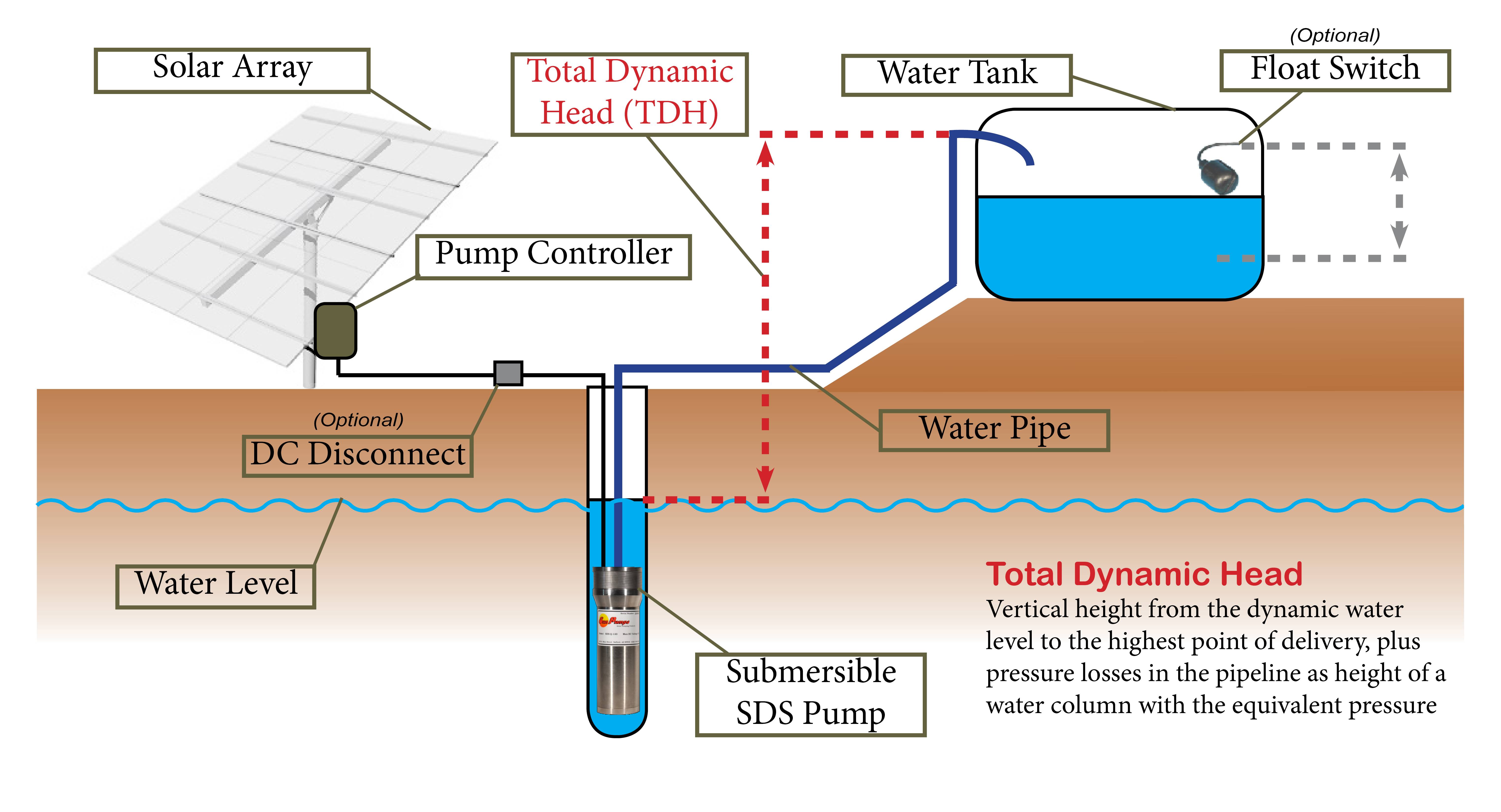
As we can see from Figure 1 above, most simple solar water pumping systems contain the following major components. There may be small or large design differences between systems - consult with a SunWize engineer if questions.
 The Solar Array in your pumping system is responsible for producing the power that will enable the pump to operate. The pump will only operate when there is sufficient solar power being produced from the array. For this reason, no water will pump at night. In rare instances where continuous pumping is required, batteries could be added to the system, but in most applications more solar and/or a large pumps are simply used to achieve whatever daily flow rates are required from just the period that the sun shines.
In small diaphram pumps, typically only about 200W of solar may be needed to achieve flow rates of between approximately 50 to 1400 gallons per day, depending on solar system size, pump size, pumping depth, and solar resources at the site. For larger centrifugal pumps, larger arrays may be strung in series to achieve higher voltages (sometimes in excess of 300VDC) in order to pump substantially larger quantities of water (tens of thousands of gallons per day).
Looking for more information on solar modules? Check out these SunWize Tech-Notes
The Solar Array in your pumping system is responsible for producing the power that will enable the pump to operate. The pump will only operate when there is sufficient solar power being produced from the array. For this reason, no water will pump at night. In rare instances where continuous pumping is required, batteries could be added to the system, but in most applications more solar and/or a large pumps are simply used to achieve whatever daily flow rates are required from just the period that the sun shines.
In small diaphram pumps, typically only about 200W of solar may be needed to achieve flow rates of between approximately 50 to 1400 gallons per day, depending on solar system size, pump size, pumping depth, and solar resources at the site. For larger centrifugal pumps, larger arrays may be strung in series to achieve higher voltages (sometimes in excess of 300VDC) in order to pump substantially larger quantities of water (tens of thousands of gallons per day).
Looking for more information on solar modules? Check out these SunWize Tech-Notes
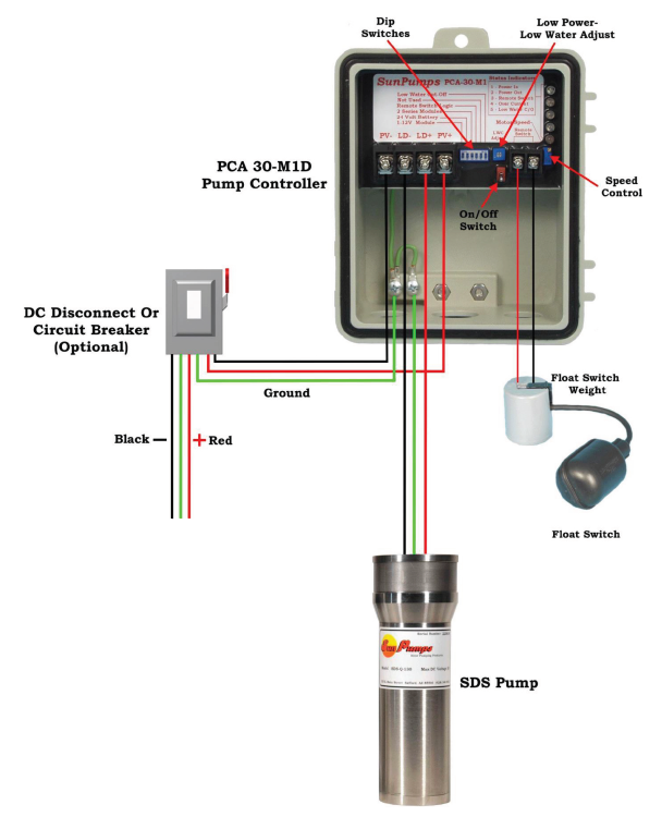 The pump controller is the interface between the solar array and the water pump. While controllers may come in a variety of configurations, most are micro-processor controlled power converters designed to produce the appropriate AC or DC power for the water pump. The controller is responsible for maximizing daily water delivery while also protecting the pump and power source from any electrical irregularities.
SunWize Sun Pumps Water Pumping Kits (WPK-SP) contain the PCA-30M1D controller, which we will briefly discuss here.
The PCA-30M1D controller is designed for use with SunPumps SDS series pumps. This controller will regulate the output voltage to 30VDC max.
Specifications
The pump controller is the interface between the solar array and the water pump. While controllers may come in a variety of configurations, most are micro-processor controlled power converters designed to produce the appropriate AC or DC power for the water pump. The controller is responsible for maximizing daily water delivery while also protecting the pump and power source from any electrical irregularities.
SunWize Sun Pumps Water Pumping Kits (WPK-SP) contain the PCA-30M1D controller, which we will briefly discuss here.
The PCA-30M1D controller is designed for use with SunPumps SDS series pumps. This controller will regulate the output voltage to 30VDC max.
Specifications
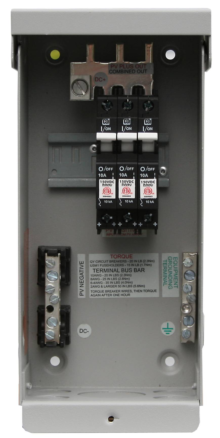 In some systems it may be helpful or safer to include a DC Disconnect in between the solar array and the pump controller. Being able to quickly disconnect the solar array from the controller will allow for easier testing and maintenance work should it ever be required.
The DC disconnect is typically nothing more than a single circuit breaker. Often times the breaker is housed in a stand-alone outdoor rated
In some systems it may be helpful or safer to include a DC Disconnect in between the solar array and the pump controller. Being able to quickly disconnect the solar array from the controller will allow for easier testing and maintenance work should it ever be required.
The DC disconnect is typically nothing more than a single circuit breaker. Often times the breaker is housed in a stand-alone outdoor rated 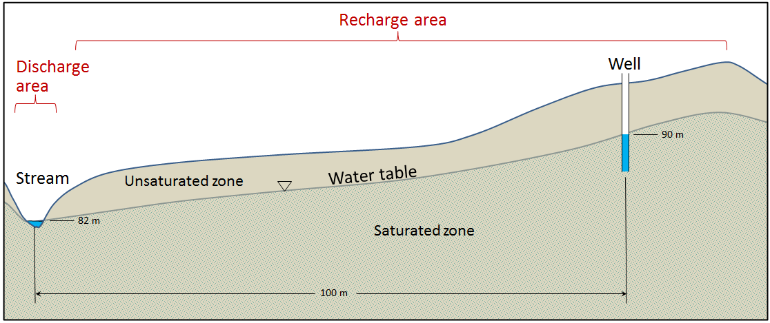
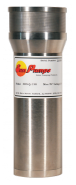 The submersible pump unit is responsible for physically moving the water from below ground to its final destination, whether that's a tank or a direct outlet. Comprised of a motor and a pump.
The SDS line of submersible pumps from SunPumps are a great option for providing simple and moderate flow solar water pumping systems. Designed for use in 4" inside diameter and larger wells, the SDS pumps feature Total Dynamic Head (TDH) of up to 230 ft. Total water production values, depending on site and system design, may be between 50 and 1,400 gallons per day. SDS Pumps are pollution-free, corrosion-free, and quiet.
The submersible pump unit is responsible for physically moving the water from below ground to its final destination, whether that's a tank or a direct outlet. Comprised of a motor and a pump.
The SDS line of submersible pumps from SunPumps are a great option for providing simple and moderate flow solar water pumping systems. Designed for use in 4" inside diameter and larger wells, the SDS pumps feature Total Dynamic Head (TDH) of up to 230 ft. Total water production values, depending on site and system design, may be between 50 and 1,400 gallons per day. SDS Pumps are pollution-free, corrosion-free, and quiet. 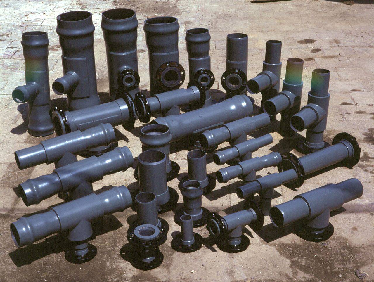 This is the pipe, or series of pipes, that connect the water pump to the final pumping location. The water piping information is important because it will be used in calculating the Total Dynamic Head, or TDH, which is required to select the appropriate solar pump for your system and application.
Your piping information may have material considerations (what type of plastic or metal or other material is used), joint considerations (types of elbows, tees, couplers, reducers, etc.), and connection considerations (fasteners, welding, soldering, etc.).
This is the pipe, or series of pipes, that connect the water pump to the final pumping location. The water piping information is important because it will be used in calculating the Total Dynamic Head, or TDH, which is required to select the appropriate solar pump for your system and application.
Your piping information may have material considerations (what type of plastic or metal or other material is used), joint considerations (types of elbows, tees, couplers, reducers, etc.), and connection considerations (fasteners, welding, soldering, etc.).Pumping Rate & Well Design
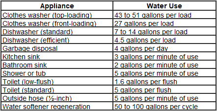
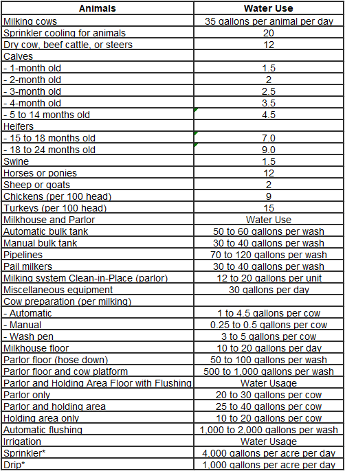
Water pumps are typically specified as having a specific Gallons per Minute (GPM) production given a specific solar array size and TDH depth. This value is multiplied by 60 (minutes in an hour), and then multiplied again by the number of sun hours for your project location. Multiplying the hourly production rate with the number of hours the sun shines at full power will give you the total gallons of water pumped per day (Gallons per Day). Typically the Gallons per Day metric is what is used to size and design the solar water pumping system. It's the responsibility of the user or designer to determine how much water is required for the specific application. It's always helpful to be conservative when estimating.
Finally, make sure that the total well casing diameter is sufficient to support the pump you plan on using. Consult the pump manufacturers specification sheets for details on minimum well casing diameter.
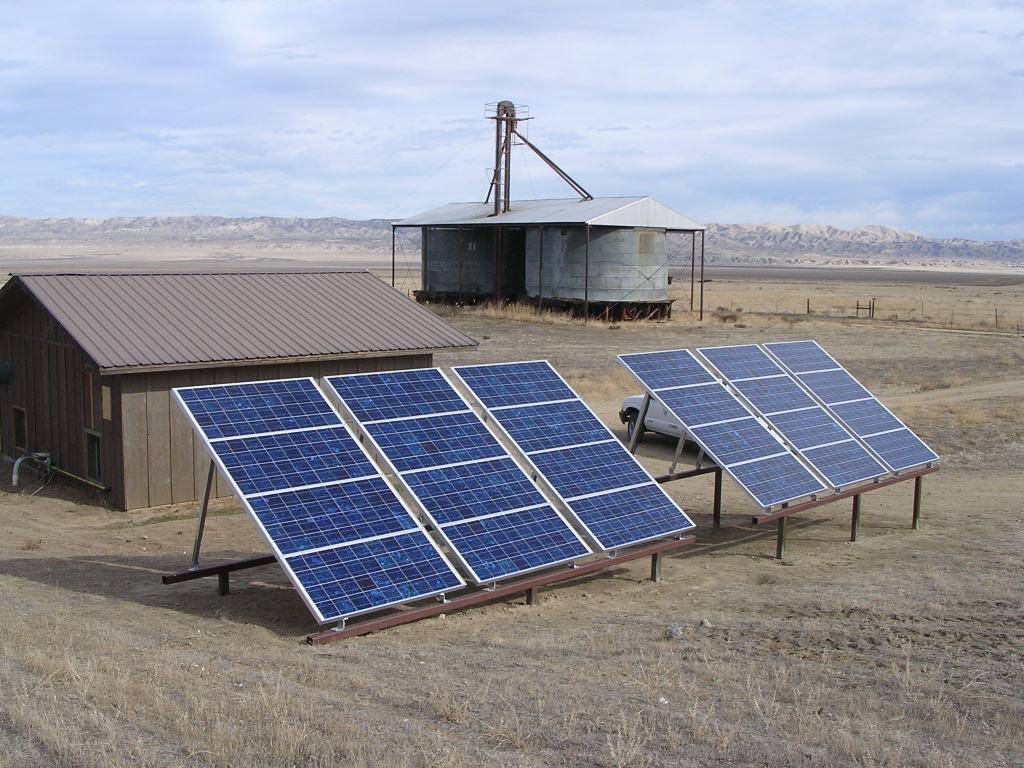
Solar Resources & Site Location
One of the most important considerations when designing and selecting an off-grid solar water pumping system is the solar resources that are available at the project location. Since solar energy is the sole energy source in many systems the sun resources available at the site will dictate the amount of water that is produced. In certain cases, such as with the Franklin Electric SubDrive pumps, alternate AC input for generators may be available.
Additionally, seasons significantly affect solar energy. Therefore, if specific flow rates are required at different times of year, it may be necessary to design and account for the worst case season (whether winter or a different season). In some cases and systems, poor solar resources can be compensated for by adding additional solar panels to the system. However, in other cases, the pump will limit the maximum amount of solar that can be used, which may limit the total production that can be achieved with one pump.
The below solar resources map can be used as a guideline for determining approximate solar resources. Please call and discuss your project specifications with a SunWize engineer for an exact system quote.

Total Dynamic Head (TDH) Calculations
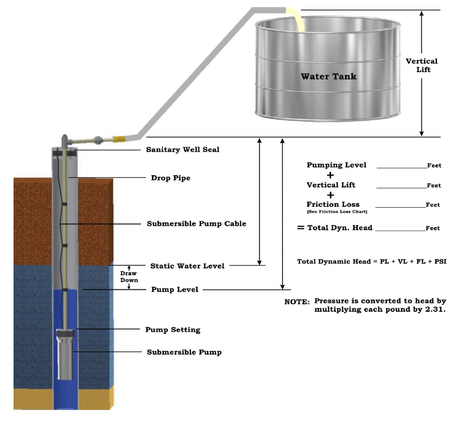
One of the most critical steps in designing ANY water pumping system is determining Total Dynamic Head (TDH). All of the SunWize Water Pumping Kit lookup tables require TDH to select the appropriate pump for your project. TDH is comprised of (3) major components: elevation head, friction head loss, and pressure head.
Figure 2: Basic Total Dynamic Head (TDH) Calculations
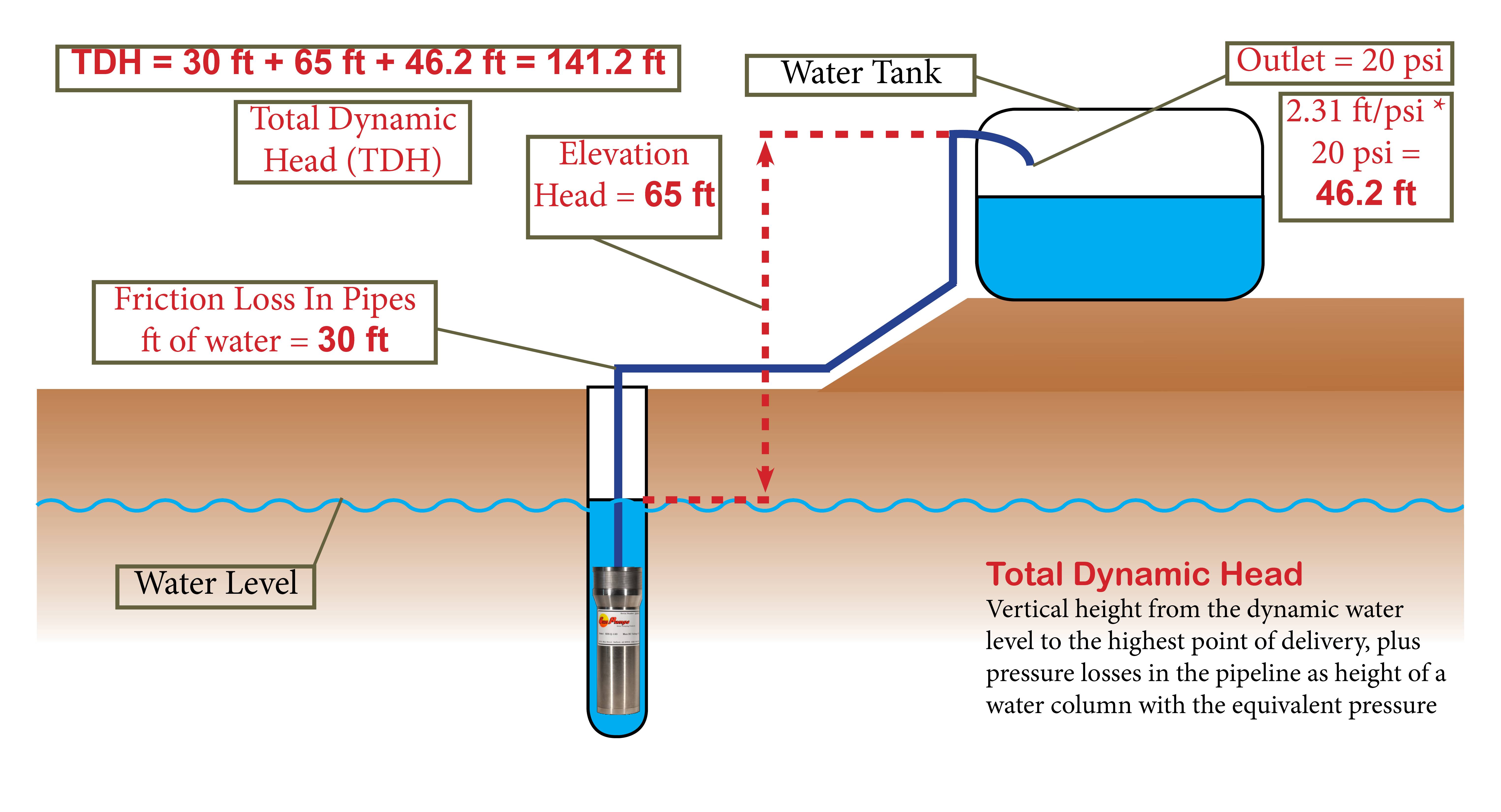
Elevation Head - 65 ft
Elevation head refers to the distance between the water level in the well (not the pump) and the maximum height the water is pumped to at the water storage tank. In the Figure 2 example above the total elevation head is 65 ft. Remember to only count the vertical distance that the water has to travel to fight gravity.
Pressure Head - 46.2 ft
The pressure head represents the amount of water pressure at the outlet of your water pipe. This could be an open pipe into the water storage tank or a water hose or other pressurized outlet. If no pressure head is present then this value can be ignore or set to zero. In cases where pressure head is present, simply multiply the pressure at the outlet in PSI by the equivalent pressure of a column of water, which is equal to 2.31 ft / psi. In our example above, an outlet PSI of 20 would equate 46.2 ft of additional head in our total dynamic head calculation.
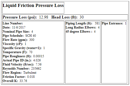
Friction Loss - 30 ft
Calculating friction losses in water piping systems is the most challenging aspect of determining your total dynamic head (TDH). We recommend utilizing any number of free online tools to help you calculate what your total friction losses are.
Follow these general steps to calculate your piping system's friction losses.
- Determine the total length of pipe that the water will travel through. This includes both horizontal and vertical distances, as well as any pipe sections at an angle.
- Go to https://www.freecalc.com/fricfram.htm or other similar sites to calculate friction losses given piping specifications.
- Enter piping specifications, including pipe size, pipe schedule, piping material, flow rate, temperatures, and how many valves and fittings are present.
- Press calculate and use the total friction loss value in ft of head given.
Following on from our example above, let's imagine we have the following specifications:
- 4" Nominal Pipe Diameter
- Sch. 40 Pipe Size
- Clean Steel Pipe
- Flow Rate of 300 Gallons per Minute
- Piping Length = 581 ft
- (4) 90° Elbows
- (4) 45° Elbows
- (1) Pipe Entrance
Summing Total Dynamic Head (TDH)
Now that we have completed the calculations for our (3) major components of Total Dynamic Head, we simply add them together to determine what our TDH for this example, as shown in Figure 2, is 141.2 ft.
Elevation Head (65 ft) + Pressure Head (46.2 ft) + Friction Loss (30 ft) = 141.2 ft
Figure 3: Basic Total Dynamic Head (TDH) Calculations Diagram